2
Additional Items you will need:
o 3/16” Allen wrench to loosen screw holding RA
motor assembly to mount.
o 5/32” Allen wrench to loosen screw holding DEC
motor assembly to mount.
o 1.5mm Allen wrench to loosen the 4 screws
holding motor housing to motors.
o Small Phillips head screw driver
to fit the 4 screws holding the
black motor housings together.
o 1 - 2 hours time and patience.
o Cleaning alcohol, cotton swabs,
etc.
o Small towel or pad on which to work.
Procedure - Set Up:
o Read entire directions BEFORE starting)
o Move the mount to a comfortable position next to
your work space - make yourself comfortable - the
conversion takes about 1 - 2 hours depending upon
your comfort level with tools and experience. Verify
that you have all the partsneeded as listed above.
Lay them out on the table so you are not hunting
for them during the conversion. Some of the parts
are very tiny.
Tip: A borrowed muffin pan from your wife's pantry makes a
good parts sorting bin while you are working.
o Disconnect all power from the mount.
o Unplug all connections at the LXD control panel on
the RA Drive.
o Remove the OTA and dovetail from the mount.
o Remove the Counterweights and Counterweight
Shaft from the mount.
o Loosen the DEC and RA Locks - Put the mount in
Polar Home Position.
Note: Now would be a good time to test / adjust your worm
toalignment to minimize slop and play and to clean them of
the stock grease. Re-lube with a high quality lubricant. This
is a tedious adjustment but one of the most rewarding when
it comes to tracking, slewing, go-to's, etc.
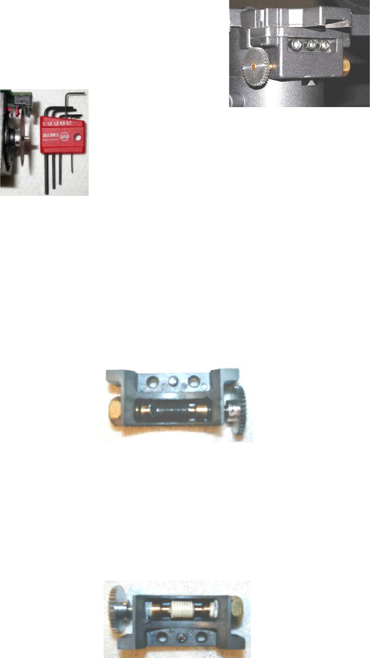
Adjusting The Worm:
After removing the mo-
tors, remove the worm
housings from the mount
by unscrewing the center
of the three screws
shown in the picture.
There are also two screws
accessable from the top
of the saddle.
Note: The three screws pictured final adjustments for align-
ment of the worm.The center bolt screws into the mount to
pull the worm against the worm gear. The two outer bolts
adjust the angle of the worm. Ideally, the center axis of the
worm shaft should be tangent to the circumference of the
worm. Do NOT touch these bolts while removing the worm
housing as they are adjusted from the factory. Only after
reinstalling the worm housing to the mount should you make
fine tune adjustments with the two outer bolts to adjust the
“tilt” of the worm relative to the worm gear. The two outer
bolts work in a push-pull arrangement with the center bolt.
Tightening the two upper bolts will pull the worm housing
slightly upward which will also tighten the worm against the
gear. I found that a thin shim washer of nylon or brass over
these two upper bolts between the saddle and worm housing
aided in fine tuning this adjustment.
This is a picture of a stock worm in it’s housing. The
large brass nut on the end opposite the gear is for ad-
justing the amount of
“play” of the worm. Re-
moving this nut ex-
poses a threaded
sleeve which holds the
worm in place. Adjust-
ing the inner sleeve will
be the critical adjust-
ment. The worm does NOT have to “spin” freely - just
turn in a smooth non-binding motion.
If properly adjusted, you should be able to grab the top
of the mount (saddle) and feel no movement if you try
to twist the mount around the RA or DEC axis.
Clean out the stock sticky grease and re-lube with
Lubriplate or SuperLube. You should be able to hand
turn the gear (or pul-
ley) on the end of the
worm shaft with a
smooth non-binding
feel. When the gear
moves, the mount
should move - no slop
- no loose movement.
Push Push
Pull
PullPull
Shim Shim
Brass
Nut
Optional Tools
 (19 pages)
 (45 pages)
 Manymanuals.com
 Manymanuals.de
 Manymanuals.fr
 Manymanuals.it
 Manymanuals.pl
 Manymanuals.cz
 Manymanuals.es
 Manymanuals-pt.com
Comments to this Manuals