Assembling The Mount & Tripod ...
(con’t)
(the one with the star) is roughly pointing at your target
object. Remove the Polar Scope Cover (#18), loosen the
DEC Lock (#17) and turn the cradle base so it is pointing
east-west in relation to the north leg. Lock the Dec Lock.
Looking through the Polar Scope eyepiece, use the Azi-
muth Adjustment Knobs (#27) and the Latitude Ad-
justment handle (#26) to align the cross-hair on your tar-
get object.
Loosen the RA Lock (#33) and rotate the mount 90 de-
grees to your right so that the Counterweight Bar (#22)
is now pointing to the left of the mount - horizontal to the
ground. If the cross hair moved off of your target, you will
need to take a small allen wrench and adjust the three
small allen screws on the Polar Scope ring up against the
setting circles. Make small adjustments to remove HALF
of the error.
Now rotate the head 180 degrees to the left so that the
Counterweight bar is now pointing to your right and hori-
zontal to the ground. Again, adjust the screws to remove
HALF of the error.
Keep repeating the procedure - moving the head back and
forth and making fine adjustments - each time removing
HALF the error - until the cross hairs stay centered on
your target. Now your Polar Scope is aligned to your mount.
Tip: Replacing the tiny allen set
screws with longer, larger headed
screws of the same thread will make
adjustments a lot easier. Available at
most hardware stores. Alternate tight-
ening and loosening screws. Do not
overtighten.
Polar Home Position ...
Throughout the manual, you will be instructed to place
the mount in Polar Home position (Fig. 16a & 16b on
Page 17). This is the basic starting point for all setup and
GoTo alignment procedures. Here is a quick and easy way
to assure good alignments each and every time. Remove
the OTA / Rings assembly and counterweights before pro-
ceeding.
Tip: NEVER remove the counterweights while the OTA is
mounted. Always remove the OTA first when disassembling
your scope.
Your scope may have come with two pairs of small black
and white arrows stuck to your mount on the RA and DEC
axis pivot seams. They may or may not be accurately placed
- this procedure will insure that they are correct. You can
do this inside in the comfort of your home.
Remove the LXD55 head from the tripod. Adjust the legs
so that they are extended about halfway and the tripod is
level. The easiest way is to place a small torpedo level
across the head of the tripod. Adjust the legs until the
bubble indicates level. Rotate the level about the head 90
degrees and check again. Adjust the legs as necessary.
Keep doing this until the head is level in all directions.
Lock the legs in place.
Tip: A small Torpedo Level is
available from sears for under
$5.00. It’s the perfect size of 9”
x 1-5/8”. It has a magnetic strip on one edge and three bubble
vials. Once you have the tripod level, you can glue a small
round Bullet Level on the top of the
East or West or both legs. Use GE Sili-
cone Type II household cement - avail-
able at Home Depot and Lowe’s. This
will make set up a lot easier from now
on.
Reattach the LXD55 head / motor assembly to the tripod -
making sure it is tightened down snug. Do not attach the
ring assembly or OTA at this time. The counterweight bar
should be approximately centered over the North leg (the
one with the star). Loosen both the RA Lock (#33) and
DEC Lock (#17). Adjust the Latitude Adjustment
handles (#26) until the Counterweight Shaft (#22) is ex-
tending between the outer two
leg tubes of the North leg.
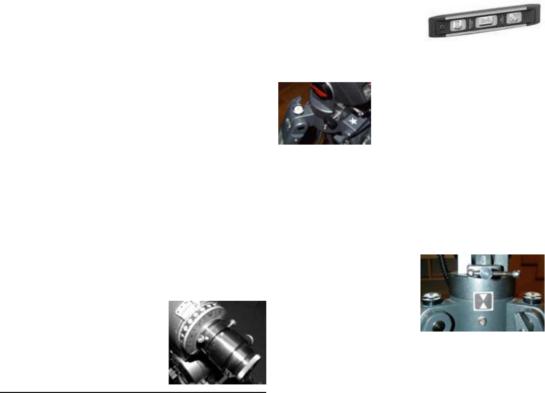
Now use the Azimuth Con-
trol Knobs (#27) to center the
shaft between the two outer
tubes. Pace an alignment ar-
row on the South side of the
mount below the Latitude Ad-
justment handle.
Tip: You can print out your own alignment arrows by down-
loading the file: Pointers.pdf available at the Yahoo Newsgroup:
LXD55telescopes (http://groups.yahoo.com/group/
LXD55telescopes/files/Pointers.PDF). This group always has
a lively discussion covering all issues - both pro’s and con’s -
along with many useful suggestions for getting the most en-
joyment out of your new telescope. If you have a question,
someone in the group will have an answer.
Holding the level against the Counterweight Shaft (#22),
adjust the Latitude Adjustment Handles (#26) until the
bar is vertical. Place the level in the Cradle Slot on the
top of the mount. This is the slot where the Cradle As-
sembly (#11) mounts. With your hand, rotate the head of
the mount until the slot and level are pointing in the north-
south direction. Adjust the Latitude Adjustment
Handles (#26) until the bubble is centered. With your
hands, rotate the head about the DEC axis 90 degrees until
the slot and level are pointing in a east-west direction.
Carefully rotate the head about the RA axis until the
bubble is centered. Repeat these two procedures until the
bubble stays centered throughout the DEC rotation. Once
it reads level throughout the rotation, Lock the RA Lock
(#33) and apply one set of alignment arrows along the RA
housing seam on the east side of the RA housing.
2
 (12 pages)
 Manymanuals.com
 Manymanuals.de
 Manymanuals.fr
 Manymanuals.it
 Manymanuals.pl
 Manymanuals.cz
 Manymanuals.es
 Manymanuals-pt.com
Comments to this Manuals